Data Logger Project
This page is a project log for a personal project I undertook in Junior year.
Note: Click on images in the project log to open them up in an enlarged modal!

Introduction
I met a visiting professor, Prof. Shane Johnson, who teaches at the Shanghai Jiao Tong University(SJTU), who was describing a problem he needed help with. Shane specializes in the field of simulation, and wanted to simulate cardboard boxes and the kinds of forces they experienced as they were being shipped from warehouses to consumers.

Motivation
The practical reason for this is that packaging engineers have to select materials and design packaging to protect the goods contained within. There exist standard tests that can be used to certify that a package meets minimum standards of protection, but nobody has investigated if the standard itself accurately reflects the conditions that packaging goes through in real life. Furthermore, understanding the conditions a package needs to withstand can help packaging engineers optimize their designs to save on packaging costs and minimize product damage.
Process
I offered to help build a battery-powered data logger that could be placed in a package and would measure the forces it experienced while being shipped. I took this as an opportunity to teach myself hobby electronics and learn to put together a complete hardware package. The steps involved were:
- Selecting Components
- Prototyping on a breadboard
- Writing firmware
- Laying out schematics for a Printed Circuit Board
- Getting PCBs manufactured and debugging
1. Selecting Components
I had to consider a myriad factors in selecting components, however the chief concerns were selecting an accelerometer that had sufficient range to capture the hardest impacts and sufficient sample rate to capture an accurate signal. Mechanical shocks are very high-amplitude and high-frequency. I finally settled on an ADXL372 module with a range of +-200G and a sample rate of up to 3200Hz.
The other chief consideration was the microcontroller. I went with an ESP8266 because it was fast, cheap, and had sufficient memory to buffer many samples from the accelerometer. At this stage, we hadn't firmed up the full featureset of the data logger, so the ESP8266's WiFi capabilities were also potentially useful. The only major downside of the ESP8266 was that it was a relatively power-hungry controller.
However, some features we knew we definitely wanted were a real-time clock, an SD card reader for long-term, high-capacity data storage, and a GPS module.
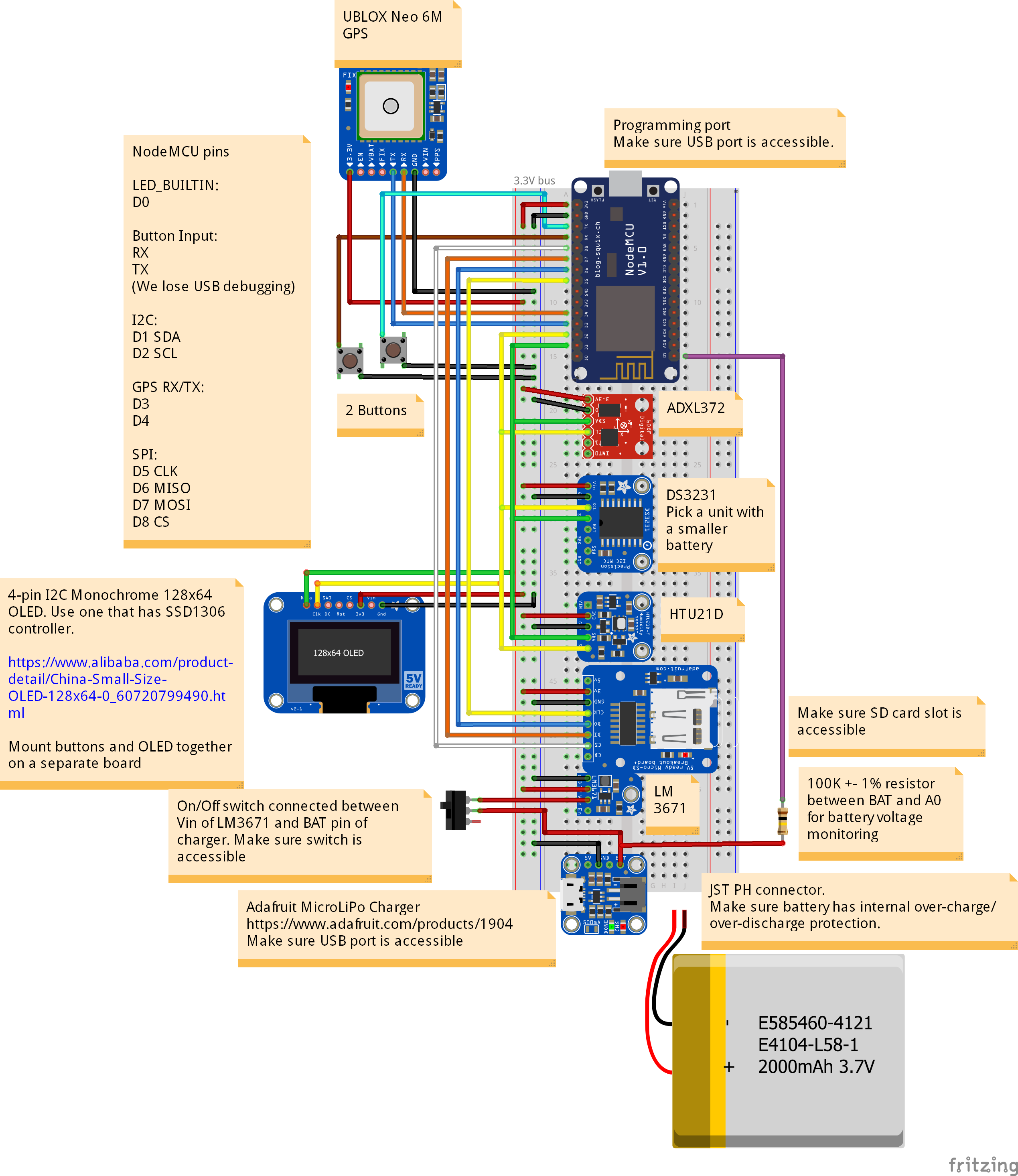
I added a few other components like a screen, some buttons, a power regulation module, a Lithium-polymer battery and a charging module.
I then drew up the following schematic in Fritzing, a free circuit layout tool.
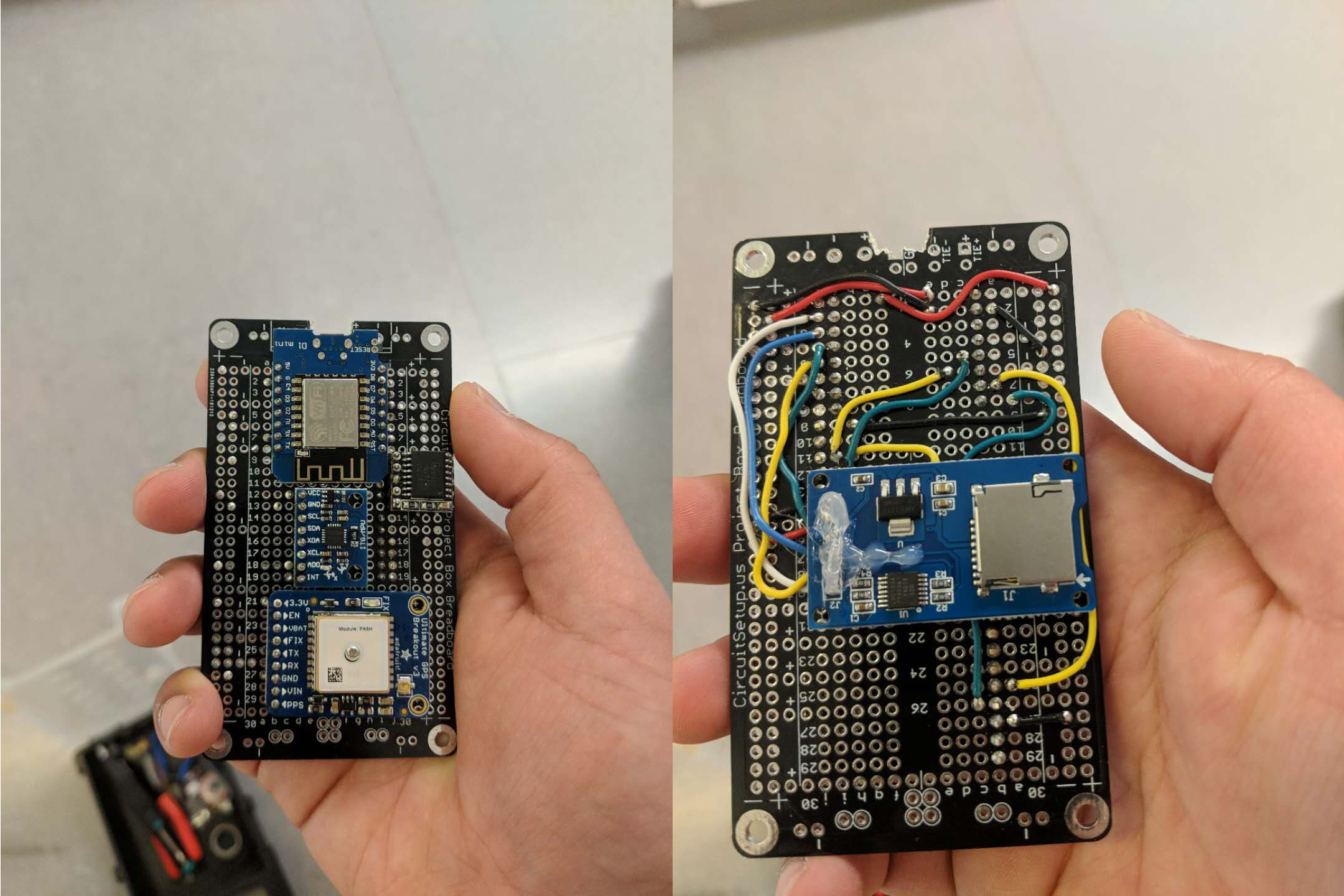
2. Prototyping on a breadboard
I assembled all the components by hand onto a breadboard so that I would have a working circuit to use for writing and debugging firmware. This also gave an idea of the dimensions of the device. This effort took quite a few hours, but I was satisfied with the final result. I omitted the Lithium-polymer battery, power regulator and charging module to simplify the prototype. For testing, I simply powered the device off the on-board power-regulator on the ESP8266 breakout I used.
3. Writing firmware
Another reason why I chose the ESP8266 was that it was supported by the Arduino platform. I was familiar with Arduino's C/C++-like language and comfortable with working in its IDE. Unfortunately, I cannot share the code here, but I followed a simple state machine design pattern. The controller would maintain a buffer of 2s of acceleration data sampled at 1000Hz (the fastest I could sample using the communication protocol I chose) by reading an acceleration value from the accelerometer every millisecond. Once it detected an acceleration value larger than some set threshold, it would devote all resources to recording 2 more seconds of data before flushing the recorded accelerations to the SD card.
Each shock event consisted of 2 seconds of data before the impact and 2 seconds of data after the impact. An equivalent drop height and orientation for the package could then be estimated from the acceleration data.
This operation was rather power-hungry, and I could have optimized it further to take advantage of the ADXL372's in-built buffering and thresholding functions, but its own buffers were too small and my choice of communication protocol did not allow me to access its advanced functionalities. Had I managed to do so, I could have greatly extended the battery life of the data logger.
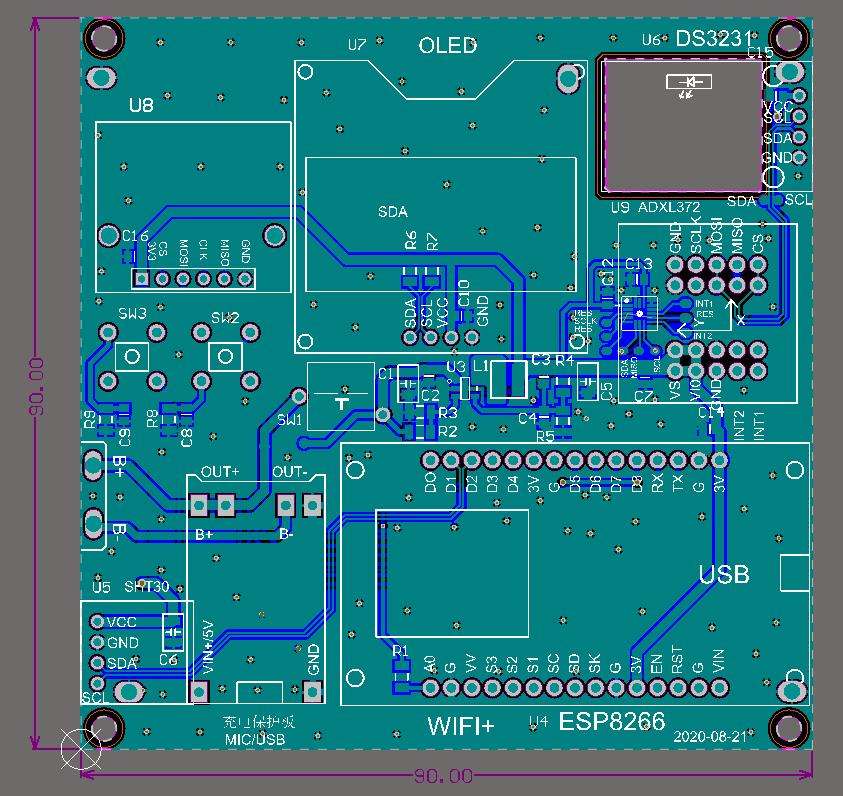
4. Laying out schematics for a Printed Circuit Board
This step was the one which I could not do myself, as while I had taught myself how to select components, wire up electronics and write firmware, I had not taught myself how to lay PCBs out. I worked with a PCB manufacturer in Shenzhen, China to produce the final layouts of the data logger PCB and assemble them.
I fully intend to eventually learn how to lay out PCBs on my own using Eagle or KiCad, but between other personal projects and full-time work, it will be something for the future.
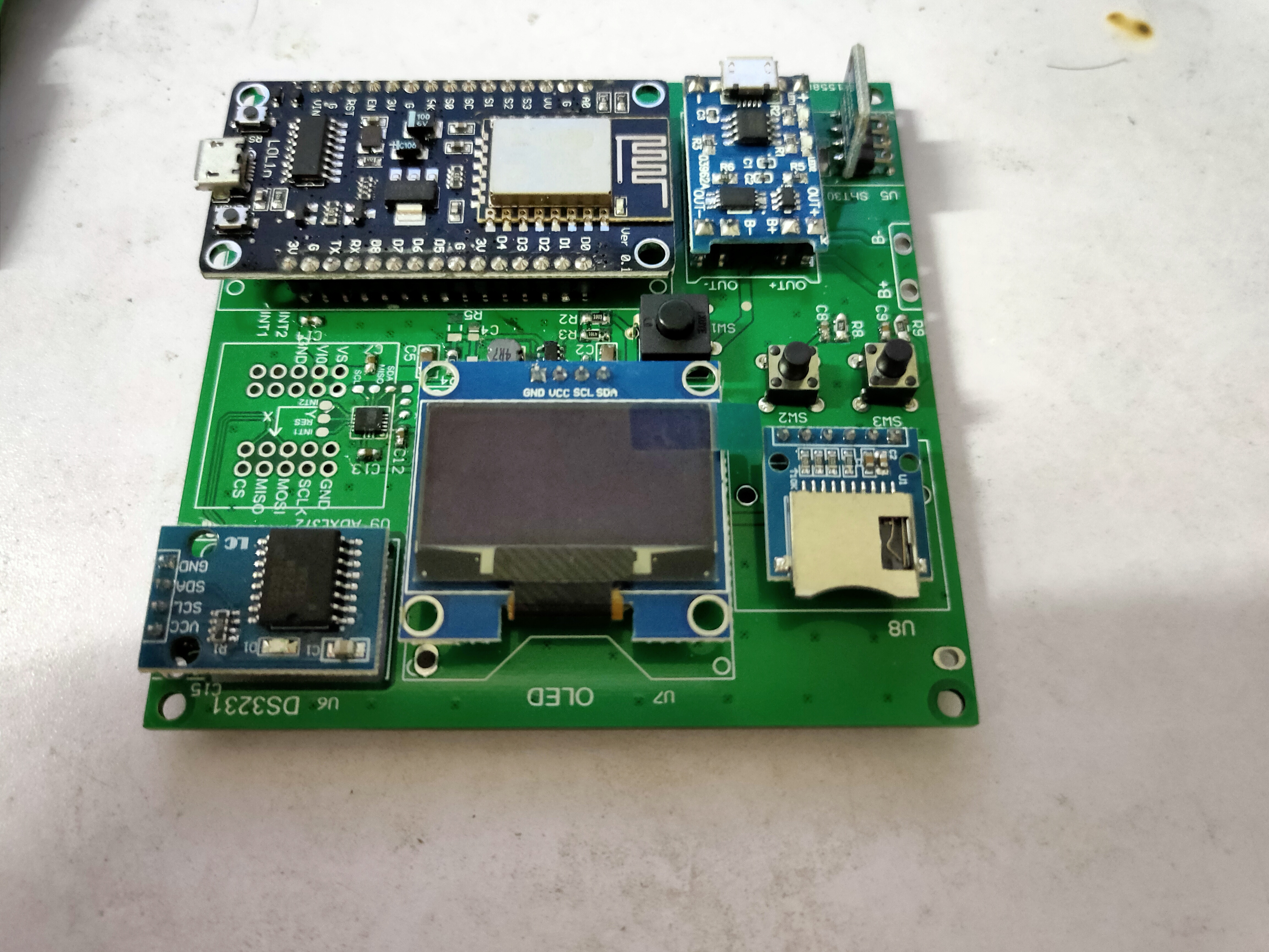
5. Getting PCBs manufactured and debugging
I eventually travelled to Shanghai, China in the summer of 2018 to meet Shane at SJTU and oversee the fabrication and delivery of the final PCBs. By this point, we had removed the GPS tracker and added more interfacing options like buttons and a screen.
The addition of the user interface made it much harder to program, since all UI operations had to happen between samples. The code I had cobbled together was finally becoming too messy to manage well, so I settled for a product with a buggy UI but robust core functionality. I added some useful tools like the ability to format the SD card and the ability to calibrate the accelerometer from the device.
Conclusion
This project was a good challenge for me and I learned plenty from it. It gave me a chance to learn and apply a whole bunch of new skills and try new things out. The data we are collecting from these data loggers (there's around 20 of them out in the wild now) is still being analyzed to see if we can determine effective drop heights and orientations accurately, however initial results are promising.